
Choose a data center UPS by the critical load it must carry, the runtime it can demonstrate and the failure and maintenance states its electrical paths must withstand. If the design has a shared dependency, too little autonomy or a bypass state that strips required protection, revise it with the responsible electrical engineer before you accept it.
Which loads does a data center UPS protect?
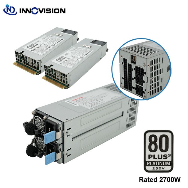
An uninterruptible power supply (UPS) holds stored energy and backs up the equipment on its protected output. Some topologies also condition the power on its way to the load. When the incoming supply is disturbed, the stored energy carries the connected equipment until an acceptable alternate supply is available or an orderly shutdown finishes.
The facility’s electrical installation sets the protection boundary. Two adjacent racks can face different outage exposure if only one sits on UPS-backed distribution. Generators, transfer equipment and downstream distribution decide what happens beyond the UPS itself. Before you change rack power, cooling systems or network availability, read the data center infrastructure dependency map.
A simplified power route runs from incoming supply through distribution, the UPS and protected distribution to the critical IT equipment. The approved electrical single-line drawing shows the real component order and any alternate paths.
Uptime Institute’s May 2026 Annual Outage Analysis names power as a leading cause of impactful outages. It lists UPS systems, transfer switches and generators among the important failure areas.
On the single-line, trace the supply to every critical-load group and mark the devices that sit outside the protected boundary.
How do you size the UPS for the load that matters?
Sizing starts with the demand of the equipment on protected power. Real power is measured in watts or kilowatts (kW). Apparent power is measured in volt-amperes or kilovolt-amperes (kVA). Power factor and the UPS model’s output limits link the two.
A 100 kVA rating gives you apparent power. Check the model’s kW output rating separately. Connected load, peaks, expected growth and any operating derating all affect the usable capacity.
Build a dated load schedule detailed enough to compare against the UPS specifications:
| Capacity evidence | Information required | Decision affected |
|---|---|---|
| Protected equipment | Connected devices; measured and forecast kW/kVA | Load the UPS supports today |
| Operating conditions | Peak behavior, power factor and load changes | Capacity in expected operating states |
| Electrical compatibility | Input/output voltage and phase arrangement | Fit with the source and downstream distribution |
| Planned additions | Growth schedule and added demand | Capacity left at the future load |
| UPS limits | Model kW/kVA ratings and derating | Usable output at the required conditions |
Keep measured readings and forecasts separate in the schedule. The UPS’s permissible operating range and charging requirements belong in the engineering evaluation too.
Uptime Institute’s July 2026 survey summary described facilities with peak rack densities of 30 kW or higher. That makes load growth easy to picture, but it is not a typical rack power figure for any particular US site.
How much battery runtime is enough, and how can you verify it?
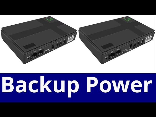
Required autonomy is the time the specified load must stay supported while the site reaches its alternate power source or finishes an orderly shutdown. The facility’s operating sequence sets that window, including cases where the standby source is delayed or unavailable.
Runtime depends on the protected load, the installed battery configuration and the state of the stored energy. Manufacturer curves, battery age and health, environmental conditions and the basis for degraded operation all feed the assessment.
A display estimate, an indicated full charge and a short self-test are different kinds of evidence from a documented loaded-runtime test. A homelab owner described seeing a sharply reduced predicted runtime when utility power failed:
Hey, our power went out and I saw our Eaton 5SC UPS pretty much immediately start a shutdown sequence of NUT clients. When I checked its display it showed it only had 5 minutes of runtime left while normally it should have around 30 minutes. You can see the drop in its charge and estimated runtime when the blackout occurred in the attached pictures. Why did this happen though? I’m not sure whether the battery is the issue because the UPS is barely 2 years old and the power only went out like twice during that time frame (and I thought Eaton’s ABM technology would preserve the battery better). The battery self-test also seems to have passed and I tried pulling the UPS’s plug today to see what happens and the battery charge didn’t drop either (the UPS showed around 30 minutes of runtime as I would expect). Thanks!
That was one homelab installation, and the cause was never established.

Compare the required window with the manufacturer’s curve for your actual load and battery configuration, then with the commissioning and test records. Those records should state the load, battery condition and degraded-state assumptions. If runtime falls short, change the battery arrangement, cut the supported load, revisit the standby-source assumption or rewrite the shutdown plan.
Which failures do N, N+1, 2N and A/B feeds cover?
N is the capacity the defined critical load requires. N+1 adds one spare component, so the remaining N components can carry the load when one is unavailable. A nominal 2N design has two full-capacity trains, and how they are connected and isolated decides what it delivers.
Source-to-load independence comes from the arrangement of switchgear, protective devices, controls and distribution. Two UPS trains can still share an upstream or downstream dependency that defeats the intended fault response.
Dual-corded IT equipment receives A and B supplies through separate input connections when the distribution paths are engineered that way. A single-corded device has one input. An appropriately designed static transfer switch can let alternate sources feed it, but then that switch, its transfer conditions and any shared path become part of the resilience assessment.
Failure-state decision matrix
Check each state below against your single-line and specified critical load.
| State to evaluate | N | N+1 | Nominal 2N / A-B | Evidence needed |
|---|---|---|---|---|
| Normal operation | Required capacity online | Required capacity plus intended spare | Configured trains carry intended loads | Connected load and source-to-load paths |
| UPS module unavailable | Remaining capacity may be insufficient | Remaining N must carry the load | Depends on train and affected component | Available kW/kVA and isolation |
| Electrical path unavailable | Load may lose its path | Extra module cannot restore a lost shared path | Alternate path must support the connected load | Independent routes, including single-input transfers |
| Maintenance or bypass | Protection follows the remaining route | Spare capacity and bypass exposure both matter | Result depends on maintenance isolation and path independence | Remaining conditioned supply and shared elements |
If the requirement is losing one UPS module, N+1 can meet it as long as the remaining modules carry the protected load. If the requirement is losing an entire electrical path, the load needs an independently usable alternate path and connections that can receive it. A 2N arrangement meets that only when its actual dependencies allow it.
Load growth can eat the N+1 spare margin. Once every module is needed to serve the updated demand, the single-module-failure capacity is gone.
For each required failure state, annotate the single-line with the remaining capacity, the feed still serving each critical load and any shared components. The electrical engineer can then judge whether the load keeps its protection when one element is lost.
Uptime Institute’s Tier criteria tie Tier III to concurrent maintainability and Tier IV to fault tolerance at the facility level. A nominal 2N UPS topology alone establishes neither.
Where do generators and transfer switches fit in the UPS chain?
Stored energy supports critical equipment while a configured generator starts, accepts load and the automatic transfer switch (ATS) or another engineered arrangement moves the supply. The documented transfer and restoration sequence sets how long the UPS must cover. If the generator fails to accept the intended load, the battery-supported interval turns into a different operating condition. The electrical engineer should compare integrated-system commissioning records for these states with the autonomy requirement.
What protection remains during static or maintenance bypass?
Bypass keeps electrical supply going but can change the conditioning, stored-energy support or redundancy a connected load receives. The effect follows from the UPS topology, the bypass source and the active operating state.
Static bypass gives an alternate route under conditions the UPS design supports. Maintenance bypass allows a defined service or isolation arrangement. In both, load continuity and remaining protection are separate engineering questions.
| Operating state | Where the load is supplied | Protection implication | Evidence to examine |
|---|---|---|---|
| Normal UPS output | Intended UPS output route | Conditioning and battery support per model and configuration | Normal-state single-line and operating records |
| Static bypass active | Configured bypass source | Conditioning and autonomy depend on remaining paths | Static bypass topology and state records |
| Maintenance bypass active | Approved service arrangement | UPS protection may be reduced on the serviced path | Isolation diagram, approved MOP and restoration evidence |
A dual-train installation with work on one UPS can keep serving the critical load on the other train. That holds only if the remaining capacity, the actual connections and the common components exposed during maintenance allow it.

During UPS servicing: An energized load may be on a bypass source with different protective characteristics. The approved method of procedure (MOP) must identify the active path and remaining protection.
Qualified operators should check the site’s bypass and isolation drawings against the MOP. The check should show which equipment stays energized, which paths keep conditioned support and what another component failure would do to the load during the work.
How do battery temperature, aging and maintenance change UPS reliability?
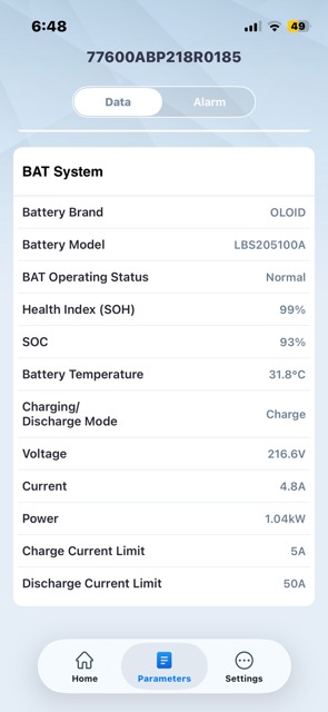
Battery condition sets the duration and reliability of stored-energy support. Temperature, charging conditions, age, chemistry and maintenance history can differ between units that look identical on a rack diagram.
The NIH September 2024 UPS Battery Failures Technical Bulletin covers battery and environmental contributors to UPS problems. A replacement date or a room-temperature reading cannot tell you the condition of every pack.
One operator described recurring battery replacements on an APC Smart-UPS SRT 8000 purchased in 2017. After investigating, the author reported sharply different readings among neighboring packs:
Thanks for all of the recommendations. It seemed like temperature control was one of the resounding recommendations so I checked and the battery pack (labeled #1) that has had the most battery replacements shows an internal temp is 42C (~107F)!! The other pack (labeled #2) was sitting at 24C (~75F) and the internal pack was 22C. This is obviously more than likely the issue. When the UPS was originally installed on the rack it was set up this way from top to bottom: Transformer module 1 —> trans module 2 -> battery pack 1 -> battery pack 2 -> UPS unit -> internal battery pack. The spacing between each rack item is zero. Everything (servers, SANs, switches, etc) is plugged into the trans modules and that obviously creates lots of heat that gets transferred over to battery pack #1. I’m not sure why the installers placed things this way but obviously it’s not ideal. I’m thinking about moving things around to make it: Transformer module 1 —> trans module 2 -> UPS -> bat 1,2,3.
The author’s heat explanation was a suspicion, not a confirmed cause. The useful clue is the gap between local pack conditions, which a room-average reading can miss.
IEEE 1188-2025 covers maintenance, testing and replacement of stationary valve-regulated lead-acid (VRLA) batteries.
Review temperature trends for each pack or string, alarms, charging history, age and test records against the battery manufacturer’s specifications. Have a qualified person investigate material anomalies before anyone changes energized equipment.
How do operating procedures, alarms and access affect UPS protection?
Facilities teams, IT staff, contractors and control-room personnel all affect the UPS operating state. Clear authorization and alarm ownership matter when work on one building system could disturb a protected electrical path.
A system administrator described an electrical contractor entering a server room during unrelated building work and shutting off the UPS without consulting IT:
Electrical contractor cut main power to parts of the building in order to do some work (nowhere near the server room or our floors) but as all doors were effectively open during powerdown he went into the server room and shut off the UPS thinking it was providing power to some circuits. IT weren’t consulted, just manager directed him to the server room and he shut it off. Critical site offline and warm site was started but caused hours of chaos. When questioned he said to the manager escorting him around that he thought there was an extra phase, manager thought it was the server room and proceeded to tell him it was OK to power it down if he needed it.
- Change authorization: Identify the affected power system, protected loads and personnel authorized to approve the work.
- Alarm response: Assign an owner for utility-loss, UPS, bypass and loss-of-protection notifications.
- Restoration record: Document the approved work, the equipment’s returned operating state and unresolved exceptions.
How should UPS efficiency, growth and cost affect the design choice?
UPS electrical losses add to operating energy and to the heat the facility must remove. Evaluate efficiency at the installed configuration’s normal and expected load levels, using the model’s part-load performance data. Before you change PUE measurements, WUE measurements or facility meters, read the data center energy-efficiency measurement guide.
The US Department of Energy’s 2024 Best Practice Guide for Data Center Design says modern double-conversion UPS systems can reach 95% efficiency or higher in some operating conditions. Its example compares 90% with 95% under the guide’s stated conditions.
A high-capacity unit running well below its intended load can perform differently from its published peak-efficiency figure, and load growth shifts the load factor behind your loss estimates.
Electricity, heat removal, battery replacement, maintenance and testing all belong in the lifecycle comparison among options that meet the required resilience objective.
Compare the proposed model’s part-load efficiency curve with monitored load and the approved growth forecast. Where the data exists, quantify the electrical losses under those conditions and keep the assumptions in the evaluation.
Which standards and tests should confirm the design before it is trusted?

Acceptance evidence has to match the claim. Different frameworks govern UPS product safety, battery maintenance, emergency power and facility availability.
| Framework | Relevant scope | Additional evidence still needed |
|---|---|---|
| UL 1778 | UPS equipment safety and compliance | Installed-system behavior during required states |
| IEEE 1188-2025 | Stationary VRLA maintenance, testing and replacement | Battery-system condition and chemistry-specific records |
| NFPA 110 and potentially NFPA 111 | Applicable emergency/standby and stored-energy emergency-power contexts | Facility classification, adopted edition and AHJ determination |
| Uptime Institute Tier criteria | Facility-level concurrent maintainability or fault tolerance | Facility design and required verification/certification evidence |
For a US site, the responsible engineer should identify the code provisions that apply and confirm the adopted edition and enforcement requirements with the jurisdiction or authority having jurisdiction (AHJ).
A documented engineering acceptance package connects:
- Design basis: Approved single-line and protected-load schedule.
- Capacity and autonomy: Model specifications, load-specific runtime data and commissioning results.
- Failure and maintenance states: Remaining power paths, bypass/MOP evidence and integrated-system test records.
- Battery and operations: Condition history, alarm routing, maintenance sign-offs and restoration evidence.
For each required fault, transfer or maintenance state, the acceptance record should name the protected load, expected supply and protection, acceptance criterion, observed or assessed result, and supporting evidence. Label conditions evaluated by analysis separately from those demonstrated in tests. Substantial load additions, changed batteries, topology modifications and post-incident repairs can trigger revalidation of the affected evidence.