Evaluate a data center as one connected system of power, cooling, network, and operations. The deciding question is whether those paths and the maintenance arrangements support your workload and its failure tolerance. Read each Tier or Rating certificate only within the scope it assessed. Trace the dependencies and request design and test evidence before you choose or change infrastructure.
What does data center infrastructure include?
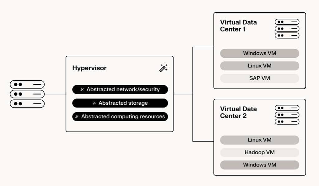
Data center infrastructure includes the servers, storage, and networking equipment that run applications, plus the electrical, mechanical, physical-security, monitoring, and operational systems that keep that equipment working. The building and its services are part of the system, even when the customer sees only a rack or a cloud service.
A rack of healthy servers still needs stable power, a way to remove heat, network connectivity, and authorized people who can respond when something fails. Some of those dependencies sit well outside the building.
| Infrastructure layer | Representative components | What it supports |
|---|---|---|
| IT equipment | Servers, storage arrays, network devices | Computation, data access, and application traffic |
| Electrical | Utility connections, switchgear, UPS, generators, power distribution | Continuous delivery of usable power |
| Thermal | Airflow management, cooling units, pumps, chillers, heat rejection | Acceptable conditions at equipment inlets |
| Connectivity | Switching, routing, external circuits, management networks | Service access, communication, and operational control |
| Physical protection | Controlled entrances, secured equipment areas, safety systems | Protection of facilities, equipment, and personnel |
| Monitoring and operations | Environmental sensors, BMS, DCIM, procedures, staff | Fault detection, maintenance, escalation, and recovery |
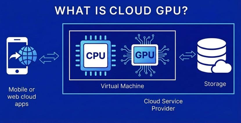
These layers explain the difference between owning a facility and consuming a service housed inside one. An enterprise may operate its data center directly. A colocation customer installs equipment in another company’s building. A cloud customer uses services backed by infrastructure the provider operates. Your access to facility records and controls changes with each model.
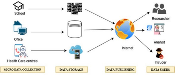
For an initial inventory, separate IT equipment, physical support systems, and operational controls, and record any responsibility with no clear owner. That shows what the workload relies on and who can act when a supporting system needs attention. The checks for identity boundaries, recovery objectives, and network routes are explained in the cloud architecture workload assessment.
Follow the three paths that keep a data center online
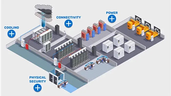
Every critical workload depends on electrical supply, heat removal, and connectivity. Each path has physical components, controls, and points where it meets another path, and an equipment count will not reveal them.
Read a design in three directions:
- Power path: A source supplies electricity through switching, protection, and distribution equipment until it reaches the rack and the server power supplies.
- Thermal path: Servers produce heat, cooling equipment collects or transfers it, and the mechanical system moves it away from the IT environment.
- Connectivity path: External and internal networks carry service traffic, while management and control communications support monitoring, storage coordination, and recovery.
A shared dependency can affect several apparently separate systems. Two electrical branches might start at the same transformer. Separate cooling units might rely on common pump controls. A resilient storage arrangement might send witness-server traffic through a single management switch.
This is a common-mode failure: one event hits several components or paths because they share a dependency.
When physical separation fails to provide independence
During a planned transformer change, a participant in r/sysadmin reported sharply different outcomes for two server rooms:
Yesterday we had to switch both of our data centers to emergency generators because the company’s power supply had to be switched to a new transformer. The first data center ran smoothly. The second one, not so much. From the moment the main power was cut and the UPS kicked in, there was a crackling sound, and a few seconds later, servers started failing one after another—like fireworks on New Year’s Eve. All the hardware (storage, network, servers, etc.) worth around 1,5 million euros was fried. Unfortunately, the outage caused a split-brain situation in our storage, which meant we had no AD and therefore no authentication for any services. We managed to get it running again at midnight yesterday.
In a later update to that post, the author clarified that the two so-called data centers were rooms about 200 meters apart that shared a transformer. The author also tied the storage split-brain to a malfunctioning management switch that blocked communication with a partner or witness server.
Two details matter for evaluation: the shared electrical source and the management-network dependency that crippled recovery.
A documented power and cooling cascade
On July 15 and 16, 2026, Google Cloud reported a 3 ms utility-voltage disturbance at its Netherlands europe-west4-a facility, followed by power-transfer and cooling-control problems. Its incident report describes data-hall temperature reaching 44°C, protective workload shutdowns, and a multi-service interruption lasting 14 hours 55 minutes; affected services experienced different impact durations.
An electrical disturbance spread through backup-power arrangements and cooling controls before it reached applications.
Pick one critical workload and trace its electrical, thermal, and connectivity dependencies on separate diagrams. Mark every component that more than one path shares, including control power and management communications.
Electrical infrastructure: how power reaches the rack
Electrical infrastructure delivers usable power to IT equipment under the operating conditions and interruptions the facility is designed to handle. It includes supply equipment, protection, distribution, alternate power, and the controls that coordinate them.
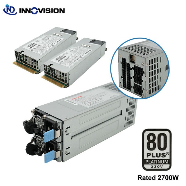
A typical facility uses a utility connection, transformers, switchgear, an uninterruptible power supply (UPS), generators or diesel rotary UPS equipment (DRUPS), automatic transfer switches, power distribution units (PDUs), remote power panels (RPPs), and rack-level feeds. The exact arrangement varies by design.
Each component has its own job. A UPS keeps power continuous during certain supply interruptions or transitions. An alternate source carries the load when utility power is gone. Distribution equipment routes and protects the supply on its way to the IT load.
What A/B power distribution means
Two rack feeds labeled A and B give distinct supply routes under a defined design. How independent they really are depends on the upstream sources, distribution components, protective devices, controls, and connected loads.
If one feed drops, a dual-power-supply server stays up only when the other branch can carry the full load and the transfer gear switches properly.
In the Google Cloud incident, one supply side completed its transfer while other parts of the distribution and backup-power system failed or hit load limits.
Detailed backup-power selection and configuration belong in the UPS and electrical redundancy guide.
Cooling and airflow at equipment inlets

IT equipment produces heat that the facility has to remove. Cooling performance depends on conditions where servers draw in air or receive coolant, and on the mechanical systems that carry the heat away.
In an air-cooled rack, cool supply air enters the equipment and warm exhaust leaves it. Hot-aisle and cold-aisle layouts keep those streams apart. Poor airflow management lets warm exhaust recirculate to equipment inlets, or lets conditioned air bypass them.
A room thermometer can show an acceptable average while individual racks see different inlet temperatures. Place sensors where the equipment draws air, because that is the condition that counts.
ASHRAE defines recommended and allowable environmental envelopes for different equipment classes. The limits that apply depend on the equipment, its operating conditions, and the manufacturer’s requirements.
Where the heat goes
Facilities use computer room air handlers (CRAHs), computer room air conditioners (CRACs), chilled-water loops, pumps, chillers, and other heat-rejection equipment.
The US Department of Energy illustrates one evaporative configuration in which heat moves from IT equipment through room cooling and water loops to a cooling tower. Other facilities combine air, water, refrigerant, and direct liquid cooling differently.
Raised floors distribute airflow in some facilities; other layouts route air and cabling differently. The raised-floor infrastructure guide addresses that design decision.
The working environment matters
Containment affects the conditions people work in during equipment installation and maintenance. A colocation customer described a concern near a hot-aisle barrier:
I recently moved into a colo cage that has hot aisle containment and the plexiglass is building static. Today when entering and leaving I noticed a tingle like I was being shocked multiple times. When I ran my arm along the plexiglass I could feel the static build. Has anyone experienced this or better yet resolved this? If so how? Can you bond/ground plexiglass?
The author suspected static electricity, but the cause was never confirmed. Treat it as a working-condition issue for the facility review, and leave any electrical safety assessment to qualified personnel.
Compare rack-inlet temperature records, sensor locations, alarms, and the thermal or airflow diagram against the equipment’s environmental envelope. The data center cooling comparison covers technology selection and airflow trade-offs in more detail.
Network, storage, physical security and facility controls
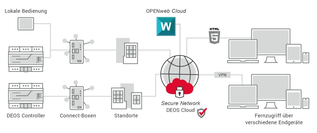
Applications need reachable networks, storage, and management systems even when servers have power and cooling. Production traffic, storage interconnects, and management communications can take different routes, and the deployed architecture decides how each failure plays out.
Some clustered storage systems rely on witness or quorum communication. If that path fails, working hardware can stop serving or fail to recover normally. Other storage architectures coordinate differently.
Physical access shapes response too. Authorized staff must reach equipment during incidents, while access controls keep uncoordinated work away from critical systems.
Building management systems (BMS) and data center infrastructure management (DCIM) tools report on electrical equipment, cooling, environmental conditions, assets, and capacity. Coverage depends on the installation.
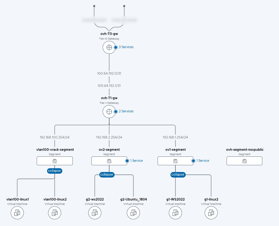
IP-connected facility controls add security and permission concerns. Govern monitoring and command access consistently with the systems they affect.
Redundancy, Uptime Tiers and TIA-942: what is certified?
Redundancy can mean spare capacity components, alternative distribution paths, or a design meant to tolerate defined failures. Each has different engineering and certification implications.
The Uptime Institute Tier Certification framework distinguishes four levels of facility infrastructure capability:
| Uptime classification | Core meaning | Maintenance and failure implication |
|---|---|---|
| Tier I | Basic capacity infrastructure | Planned maintenance of relevant capacity or distribution infrastructure requires a site-wide shutdown. |
| Tier II | Redundant capacity components | Some capacity components have redundancy, but site-wide shutdowns remain necessary for certain planned maintenance. |
| Tier III | Concurrently maintainable | Defined capacity components and distribution paths can be maintained without interrupting the IT load. |
| Tier IV | Fault tolerant and concurrently maintainable | The design tolerates specified individual equipment failures or distribution-path interruptions. |
Concurrent maintainability covers planned maintenance while the required IT load keeps running. Fault tolerance extends the design to specified failure conditions. Tier III stays exposed to certain failures and operator mistakes. Tier IV covers defined failures, but other events and operator errors can still interrupt services.
How TIA-942 Ratings differ
ANSI/TIA-942-C, revised in 2024, is a separate data center infrastructure standard with its own Rated-1 through Rated-4 classification. Those Ratings come from TIA-942 requirements and are not interchangeable with Uptime Institute Tiers.
The TIA program offers Design, Facility, and Ready certification. Design certification assesses documentation. Facility certification evaluates the completed installation and its documentation. Ready certification applies to prefabricated or modular designs assessed against the selected TIA-942 Rated level.
Why the certificate scope matters
A certificate records an assessment within its defined scope. Service-level agreements, commissioning reports, maintenance records, and measured service performance tell you more about the facility and how it runs.
Check the issuer, standard, edition, facility location, classification, certified scope, and assessment type behind any claimed credential. Those details show which property was evaluated and what you still need to confirm with facility-specific evidence.
Operations, monitoring and maintenance ownership
A redundant facility still depends on people who authorize work, interpret alarms, manage access, and restore services. Operational controls decide how the installed design gets used during maintenance and incidents.
Planned maintenance, incident response, and routine monitoring carry different responsibilities. A contractor can be qualified to work on a building system without being authorized to interrupt equipment that supports critical IT services. For uptime alerts, incident response, and restore tests, consult the website reliability diagnosis and recovery playbook.
When maintenance coordination breaks down
A contributor in r/sysadmin described a building contractor shutting down critical IT power during other electrical work:
Electrical contractor cut main power to parts of the building in order to do some work (nowhere near the server room or our floors) but as all doors were effectively open during powerdown he went into the server room and shut off the UPS thinking it was providing power to some circuits. IT weren’t consulted, just manager directed him to the server room and he shut it off. Critical site offline and warm site was started but caused hours of chaos. When questioned he said to the manager escorting him around that he thought there was an extra phase, manager thought it was the server room and proceeded to tell him it was OK to power it down if he needed it.
In the longer account, the author described failures of communication, access authorization, and notification. It is a firsthand report of how poor maintenance coordination can defeat installed protection.
Permission to enter a facility and authority to approve work that affects IT services are separate responsibilities. Each needs a defined owner.
Who receives the alarm?
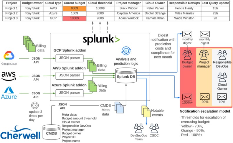
An alarm helps only if someone receives it and can investigate or escalate. A cooling alarm may need facilities expertise plus coordination with the IT team that owns the affected workloads.
| Event or condition | Signal or trigger | Ownership to establish | Coordination required |
|---|---|---|---|
| UPS or distribution fault | Electrical equipment alarm | Primary technical owner and backup | Notification to affected IT service owners |
| Cooling problem | Rack-inlet or mechanical alarm | Facility or HVAC owner and escalation contact | Equipment and workload protection decisions |
| Planned electrical work | Approved change request | Authorized maintenance approver | Facilities, IT, and relevant service owners |
| Monitoring unavailable | Loss of telemetry or management communication | Monitoring-system owner | Alternative escalation and incident response |
A colocation operator may control the facility plant while the customer stays responsible for its installed IT equipment.
Capacity, PUE, WUE and the physical limits behind efficiency claims
Electrical service, distribution capacity, cooling capability, water needs, and expansion space all limit the workloads a facility can support. Contracted rack capacity, equipment nameplate ratings, and observed IT consumption are three different quantities.
Power Usage Effectiveness
The US Department of Energy’s Federal Energy Management Program defines annual Power Usage Effectiveness as:
PUE = Annual total facility energy (kWh) / Annual IT equipment energy (kWh)
PUE is dimensionless. It compares facility energy consumption with the energy IT equipment consumes. As supporting overhead shrinks relative to IT energy, PUE approaches 1.
A lower PUE means less facility overhead per IT kWh, provided both sites measure the same way. It says nothing about useful computing output, resilience, or overall environmental performance, which need separate measures.
Water Usage Effectiveness
For the DOE site-water measure:
WUE = Annual site water use (liters) / Annual IT equipment energy (kWh)
The unit is liters per kWh of IT energy.
PUE and WUE count different resources. Cooling designs can shift demand between electricity and water depending on climate, plant configuration, operating conditions, and the measurement boundary.
The DOE FEMP cooling-water guidance provides the definitions and an illustrative evaporative cooling arrangement.
US electricity demand and infrastructure constraints
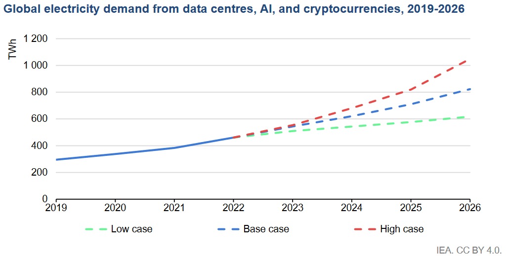
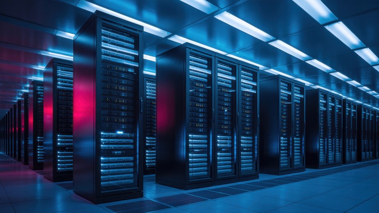
Lawrence Berkeley National Laboratory’s United States Data Center Energy Usage Report: 2025 Update, published in June 2026, estimates US data center electricity consumption at 192 TWh in 2024, equal to 4.7% of national electricity consumption. The model excludes cryptocurrency mining.
Its 2030 reference scenario reaches 649 TWh, or 11.8% of national electricity consumption. Across modeled scenarios, 2030 consumption spans 521 to 843 TWh, equal to 9.5% to 15.3%.
The figures appear in the LBNL energy usage report.
Uptime Institute’s July 2026 global survey points to pressure from power availability, cost, staffing, supply constraints, and rising rack densities. More operators now report peak rack densities of at least 30 kW. That is a peak, not a typical load.
At the facility level, you need actual rack and IT load, electrical and thermal headroom, and PUE/WUE records with stated boundaries and reporting periods.
The data center energy-efficiency guide covers methods for investigating efficiency improvements.
How workloads and operating models change the design choice
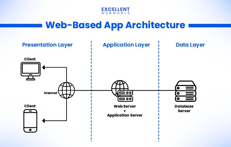
An enterprise-owned facility keeps physical infrastructure responsibilities inside the organization. A colocation tenant generally operates selected IT equipment inside a provider-managed facility. Cloud services divide responsibility according to the service model and the agreement.
A modest enterprise workload and a dense accelerator workload need different rack power, cooling, monitoring, and expansion provisions. Cooling technology depends on the equipment, the rack density, and the site.
Local utility capacity, geography, climate, water availability, physical access, failure tolerance, and expected growth also change the right answer. Match those constraints and responsibilities to your next assessment, such as closed-loop liquid cooling requirements or the colocation versus cloud responsibility comparison.
A practical infrastructure assessment: the proof behind the diagram
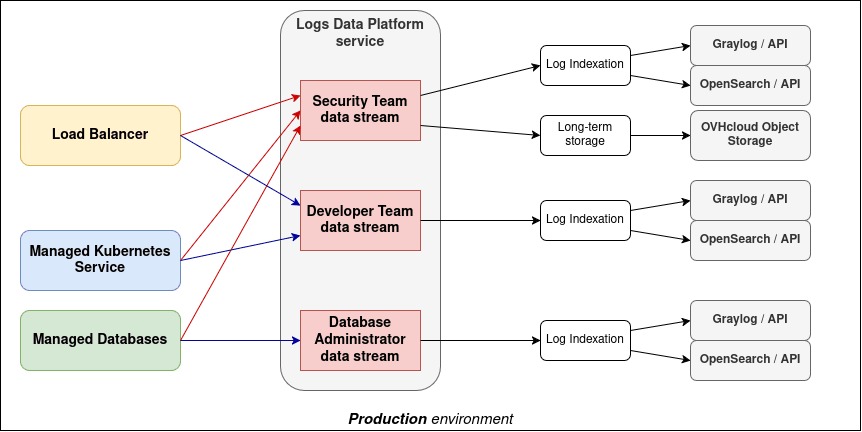
An infrastructure evaluation connects a critical workload to the systems that keep it available and to the records describing how they behave. A component inventory shows what is installed. Drawings, measurements, commissioning evidence, and operating arrangements show what was designed, what was observed, and who is responsible.
For an internal facility or a prospective colocation site, this matrix organizes the evidence.
| System or responsibility | Potential unresolved dependency | Evidence for assessment | Specialist follow-up |
|---|---|---|---|
| Electrical supply | Shared source, distribution component, or critical control | Electrical single-line, load records, commissioning scope | Power and UPS assessment |
| Cooling | Common mechanical dependency, inadequate inlet conditions, or missing telemetry | Mechanical diagram, rack-inlet records, control and alarm coverage | Cooling methods; liquid cooling |
| Network and storage | Shared switching, management, or coordination dependency | Network topology, critical-service and management inventory | Qualified network or storage review |
| Facility layout | Airflow or equipment-access constraint | Layout information and facility operating requirements | Raised-floor design |
| Energy and water | Unclear measurement boundary or resource constraint | Annual IT and facility energy, site-water records | Efficiency measures |
| Certification | Classification or design claim lacks matching assessment scope | Issuer, standard, facility scope, certificate and commissioning records | Relevant Uptime or TIA program and qualified facility specialist |
| Operational governance | Unassigned change authority, alarm ownership, or escalation responsibility | Maintenance procedures, named owners, notification and response records | Facility operator and affected IT service owners |
Sort the supplied records into three states:
- Available and consistent: The documents support the stated arrangement within the scope reviewed. Keep the records together with their stated limits.
- Incomplete: A needed diagram, measurement, or operating record is missing. Note the missing item and its owner.
- Potential shared dependency or conflict: The material points to incompatible assumptions or leaves a common component unresolved. Refer it for technical investigation.
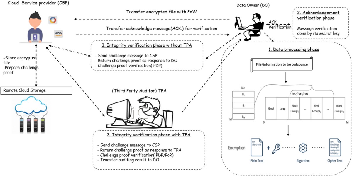
Take a hypothetical facility with two rack feeds labeled A and B. The documents show distinct downstream branches but say nothing about the upstream transformer or control relationships. That leaves the assessment open. The labels describe the intended arrangement, and only reviewed source and control documentation can establish how independent the feeds are. Missing documentation is an evidence gap, and only facility inspection and testing can establish the actual installed conditions.